
Learning to use the GPIO pins on your Raspberry Pi opens up a whole world of possibilities. The basic principles learned through beginner projects pave the way toward useful knowledge of both DIY electronics and programming.
This tutorial will show you two ways to add a button to your Raspberry Pi project. The button will be used to control an LED. Written instructions are available below the video.
You Will Need
To get started, make sure you have the following components:
- 1 x Raspberry Pi (Any will do, model 3B is used in this tutorial)
- 1 x Push Button
- 1 x LED
- 1 x 220 Ohm Resistor (Higher values are fine, your LED will just be dimmer)
- 1 x Breadboard
- Hook up wires
Once gathered, you should have components that look something like this:
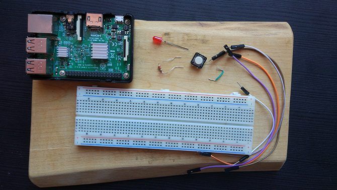
You’ll also need an SD card with the Raspbian operating system installed. The quickest way to do this is with the NOOBS (New Out Of the Box Software) image. Instructions on how to do this are available in this video:
Setting Up the Circuit
You will be using the GPIO pins of the Pi to make the circuit, and if you are unfamiliar with them our guide to Raspberry Pi GPIO pins will help. The circuit here is almost the same as in our previous Raspberry Pi LED project, with the addition of the button you’ll be using today.
Set up your circuit according to this diagram:
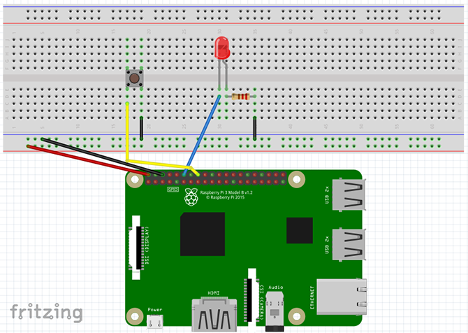
- The 5v and GND pins connect to the power rails of the breadboard.
- Pin 12 (GPIO 18) connects to the positive leg of the LED.
- One leg of the resistor attaches to the negative leg of the LED, and the other leg attaches to the ground rail of the breadboard.
- Pin 16 (GPIO 23) attaches to one side of the button, the other side attaches to the ground rail of the breadboard.
Once it’s set up, here’s how it should look:
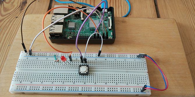
Check over your circuit to make sure it is correct, and then power up your Raspberry Pi.
Method 1: The RPi.GPIO Library
Once the Pi has booted, head to the menu and select Programming > Thonny Python IDE. A new Python script will open. If you are totally new to Python, it’s a great language for beginners and there are many great places to learn more about Python after you are done with this tutorial!
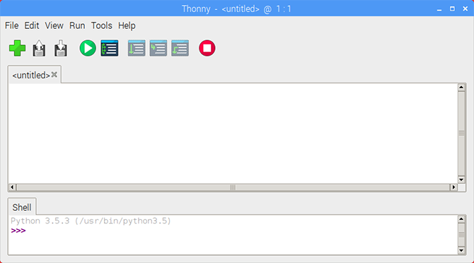
Start by importing the RPi.GPIO library, and setting the board mode.
import RPi.GPIO as GPIO

GPIO.setmode(GPIO.BOARD)
Now declare the variables for the LED and button pin numbers.
ledPin = 12
buttonPin = 16
Note that since we have the board mode set to BOARD we are using the pin numbers rather than the GPIO numbers. If that is confusing to you, a Raspberry Pi pinout chart can help clear it up.
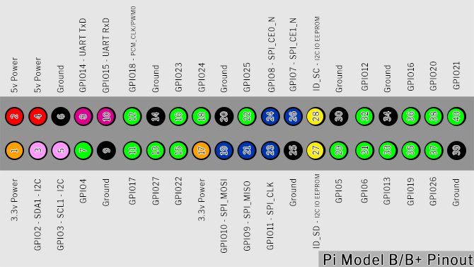
Setting Up the Button
It’s time to set up the GPIO pins. Set the LED pin to output, and the button pin to input with a pull-up resistor
GPIO.setup(ledPin, GPIO.OUT)
GPIO.setup(buttonPin, GPIO.IN, pull_up_down=GPIO.PUD_UP)
The text after GPIO.IN refers to the internal pull-up resistor of the Raspberry Pi. You need to enable this to get a clean reading from the button. Since the button is going to the ground pin, we need a pull-up resistor to hold the input pin HIGH until you press it.
Before we go on, let’s look at pull-up and pull-down resistors.
Intermission: Pull Up/Pull Down Resistors
When you configure a GPIO pin to input, it reads that pin to determine its state. In this circuit, you need to read whether a pin is HIGH or LOW to trigger the LED when the button is pressed. This would be simple if those were the only states a pin can have, but unfortunately, there is a third state: FLOATING.
A floating pin has a value between high and low, causing the input to act unpredictably. Pull-up/pull-down resistors solve this.

The above image is a simplified diagram of a button and a Raspberry Pi. The GPIO pin connects to ground through the button. The internal pull-up resistor attaches the GPIO pin to the internal Pi power supply. This current flows and the pin is safely pulled up to HIGH.
When you press the button, the GPIO pin connects directly to the ground pin, and the button reads low.

Pull-down resistors are for when the switch is connected to the power pin. This time, the internal resistor attaches the GPIO pin to ground, holding in LOW until you press the button.
Pull-up and Pull-down resistor theory is confusing at first glance, but important knowledge to have when working with microcontrollers. For now, if you don’t quite understand it, don’t worry!
Let’s continue where we left off.
The Program Loop
Next, set up the program loop:
while True:
  buttonState = GPIO.input(buttonPin)
  if buttonState == False:
    GPIO.output(ledPin, GPIO.HIGH)
  else:
    GPIO.output(ledPin, GPIO.LOW)
The while True loop continually runs the code inside it until we end the program. Every time it loops it updates the buttonState by reading the input from the buttonPin. While the button is not being pressed, it stays HIGH.
Once the button is pressed, buttonState becomes LOW. This triggers the if statement, since False is the same as LOW, and the LED turns on. The else statement turns the LED off whenever the buttonPin is not False.
Save and Run Your Script
Save your script by clicking File > Save As and choosing a file name. You can run the sketch by clicking the green Play button in the Thonny toolbar.

Now press the button, and your LED should light up! Press the red Stop button at any time to stop the program
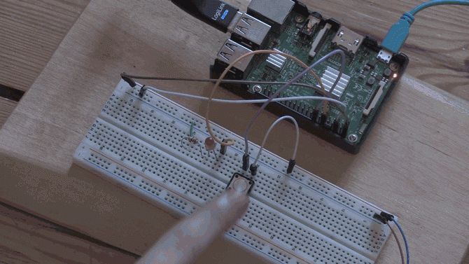
If you are having difficulties, check your code and circuit setup thoroughly for errors and try again.
Method 2: GPIO Zero Library
The RPi.GPIO library is fantastic, but there is a new kid on the block. The GPIO Zero Library was created by Raspberry Pi community manager Ben Nuttall with the intention of making code simpler, and easier to read and write.
To test out the new library open up a new Thonny file, and import the library.
from gpiozero import LED, Button
from signal import pause
You’ll notice you didn’t import the whole library. Since you are only using an LED and button, you require only those modules in the script. We also import Pause from the signal library, which is a Python library for event management.
Setting up the pins is much easier with GPIO Zero:
led = LED(18)
button = Button(23)
Since the GPIO Zero library has modules for the LED and button, you do not need to set up inputs and outputs like before. You will notice that though the pins haven’t changed, the numbers here are different from above. That is because GPIO Zero only uses the GPIO pin numbers (also known as Broadcom or BCM numbers).
The rest of the script is only three lines:
button.when_pressed = led.on
button.when_released = led.off

pause()
The pause() call here simply stops the script from exiting when it reaches the bottom. The two-button events get triggered whenever the button is pressed and released. Save and run your script and you’ll see the same result as before!
Two Ways to Add a Button to Raspberry Pi
Out of the two ways to set up the button, the GPIO Zero method seems to be the easiest. It is still worth learning about the RPi.GPIO library as most beginner Raspberry Pi projects use it. As simple as this project is, the knowledge can be used for a number of things.
Using the GPIO pins is a great way to learn and invent your own devices, but its far from everything you can do with the Pi. Our unofficial guide to the Raspberry Pi is brimming with creative ideas and tutorials you can try out yourself!
Read the full article: 2 Ways to Add a Button to Your Raspberry Pi Project
via MakeUseOf https://ift.tt/2NBqk0Q
Comments
Post a Comment